
TM 5-2410-240-23-3
0238
DISASSEMBLY CONTINUED
000238
9. Remove two screws (Figure 13, Item 1) and wrist pad cushion (Figure 13, Item 2) from bracket (Figure 13,
Item 3).
Figure 13. Joystick Control Support Wrist Pad.
0238
N OT E
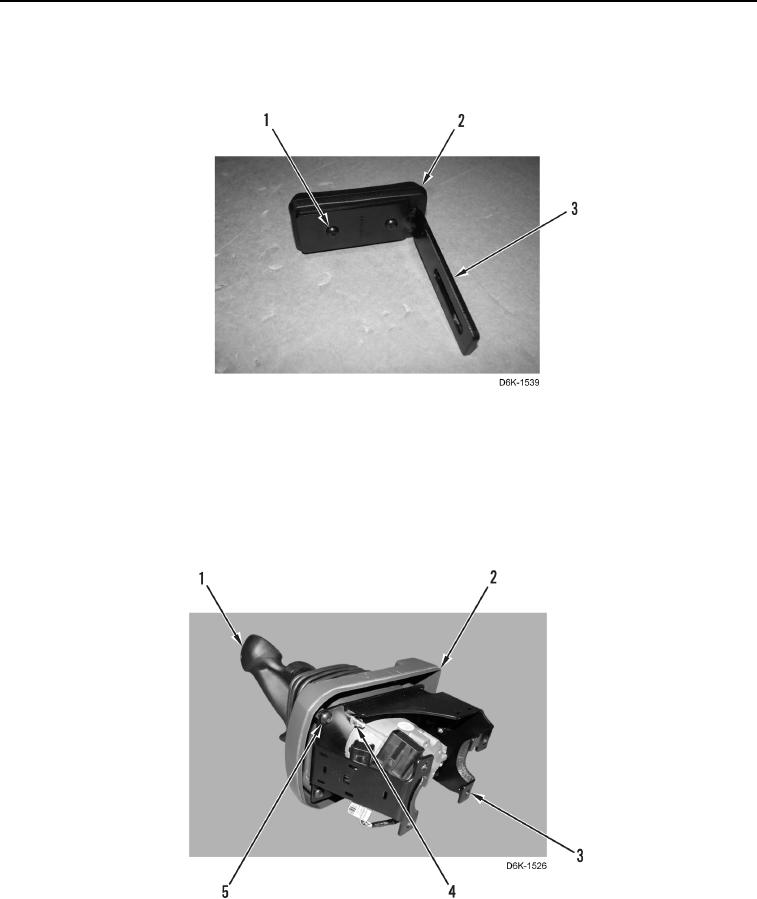
Note location of tiedown straps to aid installation.
10. Remove four locknuts (Figure 14, Item 4), joystick control assembly (Figure 14, Item 1), four screws
(Figure 14, Item 5), and cover (Figure 14, Item 2) from bracket (Figure 14, Item 3). Discard locknuts.
Figure 14. Joystick Control Assembly, Cover, and Bracket.
0238

