
TM 5-2410-240-23-3
0245
DISASSEMBLY CONTINUED
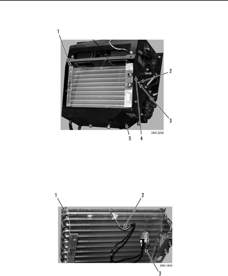
8. Remove four bolts (Figure 13, Item 2), washers (Figure 13, Item 3), side plate (Figure 13, Item 4), and
evaporator (Figure 13, Item 1) from case (Figure 13, Item 5).
Figure 13. Side Plate, Evaporator, and Retaining Hardware.
0245
N OT E
Note location and length of probe to aid installation.
9. Remove probe (Figure 14, Item 2) and evaporator temperature sensor (Figure 14, Item 3) from evaporator
(Figure 14, Item 1).
Figure 14. Evaporator Temperature Sensor and Probe.
0245

