
TM 5-2410-241-23-2
0156
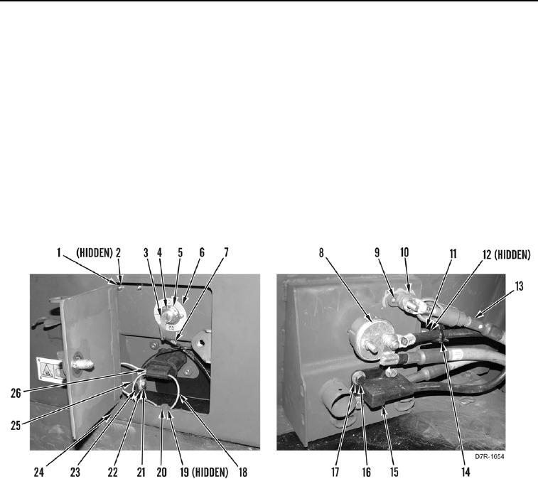
REMOVAL CONTINUED
5. Remove bolt (Figure 3, Item 21), two washers (Figure 3, Item 22), nuts (Figure 3, Item 25), and key strap
(Figure 3, Item 7) from bracket (Figure 3, Item 23).
6. Remove key (Figure 3, Item 3) from battery disconnect switch (Figure 3, Item 8).
7. Remove receptacle cable cover (Figure 3, Item 26) from receptacle cable (Figure 3, Item 15).
8. Remove bolt (Figure 3, Item 20), washer (Figure 3, Item 19), receptacle cable cover strap (Figure 3, Item 18),
receptacle cable cover (Figure 3, Item 26), and bracket (Figure 3, Item 23) from front battery box cover
(Figure 3, Item 24).
9. Remove bolt (Figure 3, Item 11), washer (Figure 3, Item 12), and ladder clip (Figure 3, Item 14) from front
battery box cover (Figure 3, Item 24).
10. Remove four bolts (Figure 3, Item 16), washers (Figure 3, Item 17), and receptacle cable (Figure 3, Item 15)
from front battery box cover (Figure 3, Item 24).
11. Remove nut (Figure 3, Item 4), two lockwashers (Figure 3, Item 5), and battery disconnect switch (Figure 3,
Item 8) from front battery box cover (Figure 3, Item 24). Discard lockwashers.
Figure 3. Battery Disconnect Connections.
0156
N OT E
Decals can not be re-used, new decal must be installed if battery box is being replaced.
Note location and orientation to aid installation.
12. Note location of decal (Figure 3, Item 6) on front battery box cover (Figure 3, Item 24).
N OT E
Arctic kit cable shown for machines equipped with arctic kit. Step 13 is for machines
equipped with arctic kit. Go to step 14 if arctic kit is not installed.
13. Position arctic kit junction block cable (Figure 3, Item 13) aside.
14. Remove two nuts (Figure 3, Item 1), lockwashers (Figure 3, Item 2), and bolts (Figure 3, Item 9), and electrical
post (Figure 3, Item 10) from front battery box cover (Figure 3, Item 24). Discard lockwashers.

