
TM 5-2410-241-23-3
0297
LIFT CYLINDER REMOVAL CONTINUED
N OT E
Tag hoses to aid installation.
Care must be taken to ensure that fluids ae contained during this service. Be prepared to
r
collect the fluid with suitable containers before disassembling any component containing
fluids.
Dispose of all fluids IAW Unit SOP.
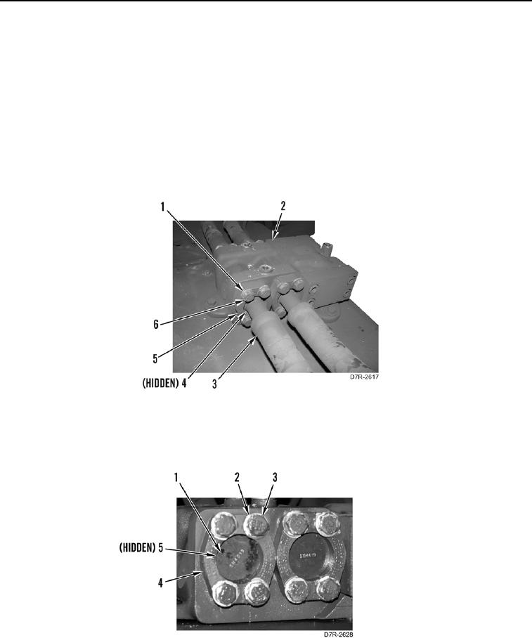
9. Remove 16 bolts (Figure 5, Item 6), washers (Figure 5, Item 1), 8 flanges (Figure 5, Item 5), 4 hoses (Figure 5,
Item 3) and O-rings (Figure 5, Item 4) from quick drop valve (Figure 5, Item 2). Discard O-rings.
10. Install caps on four hoses (Figure 5, Item 3) to prevent fluid leakage during transport.
Figure 5. Lift Cylinder Hydraulic Hoses.
0297
11. Using the removed 8 flanges (Figure 6, Item 4), 16 bolts (Figure 6, Item 3), and washers (Figure 6, Item 2),
install 4 seals (Figure 6, Item 5) and covers (Figure 6, Item 1) over open ports on quick drop valve.
Figure 6. Covers.
0297

