
TM 5-2410-240-23-1
0011
IMPLEMENT HYDRAULIC SYSTEM CONTINUED
Implement Pump Description
00011
The implement pump (Figure 2, Item 1) is a variable displacement piston pump that has the following
characteristics:
Load Sensing
Variable Pressure
Compensation for Pressure
Variable Flow
Compensation for Flow
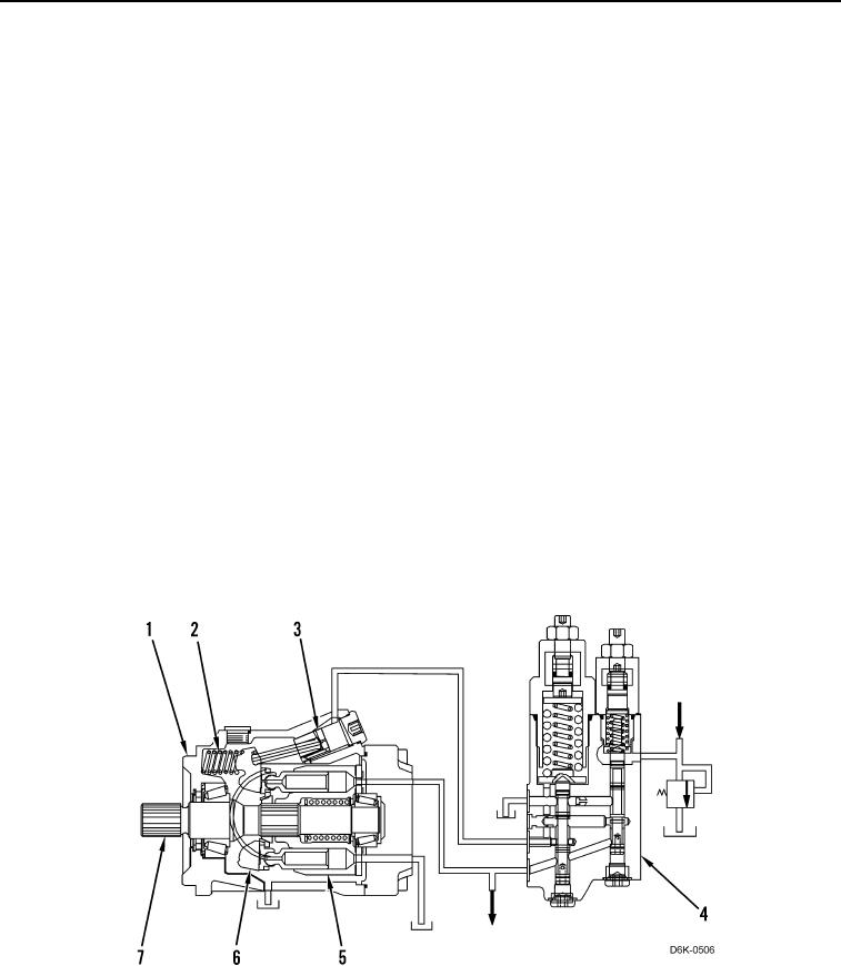
The implement pump (Figure 2, Item 1) contains the following components:
Bias spring (Figure 2, Item 2). If there is no pressureon the right side of the actuator piston (Figure 2, Item 3)
then the bias spring (Figure 2, Item 2) will hold the swashplate (Figure 2, Item 6) at the maximum angle.
Actuator piston (Figure 2,Item 3). When oil pressure increases behind the actuator piston, then the piston will
overcome the force of the bias spring (Figure 2, Item 2). This causes the angle of the swashplate (Figure 2,
Item 6) to reduce.
Pressure andflow compensator valve (Figure 2, Item 4). The pressure and flow compensator valve controls
the delivery of oil and the return of oil to the actuator piston (Figure 2, Item 3).
Piston and barrel assembly (Figure 2,Item 5). The cylinder barrel contains nine pistons. The cylinder barrel
assembly rotates whenever the engine is running. The pistons move oil into the barrel and out of the barrel.
Swashplate (Figure 2, Item 6). The an le of the swashplate controls the displacement of the implement pump
g
(Figure 2, Item 1). The angle of the swashplate causes the pistons to move in and out of the rotating barrel.
Input shaft (Figure 2, Item 7). Pump rotation is clock ise when viewed from the drive end. The piston and bar-
w
rel assembly (Figure 2, Item 5) is splined to input shaft.
Figure 2. Implement Pump.
0011

