
TM 5-2410-240-23-3
0190
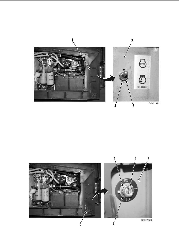
REMOVAL CONTINUED
4. Remove lockwasher (Figure 2, Item 4) from lockout switch (Figure 2, Item 3). Discard lockwasher.
5. Remove lockout switch (Figure 2, Item 3) from right rear access panel (Figure 2, Item 2) and position switch
aside.
6. Close lockout switch access door (Figure 2, Item 1).
Figure 2. Lockwasher and Lockout Switch.
0190
7. Open battery disconnect switch access door (Figure 3, Item 5).
8. Remove nut (Figure 3, Item 1) and lockwasher (Figure 3, Item 4) securing battery disconnect switch (Figure 3,
Item 2) to right rear access panel (Figure 3, Item 3). Discard lockwasher.
9. Remove battery disconnect switch (Figure 3, Item 2) from right rear access panel (Figure 3, Item 3) and
position switch aside.
10. Close battery disconnect switch access door (Figure 3, Item 5).
Figure 3. Battery Disconnect Switch and Retaining Hardware.
0190

