
TM 5-2410-240-23-3
0207
INSTALLATION CONTINUED
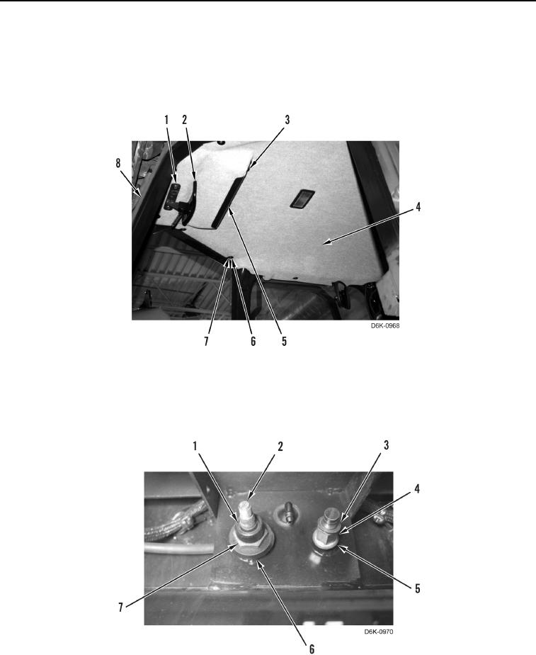
3. Install headliner (Figure 7, Item 4), six washers (Figure 7, Item 6), and bolts (Figure 7, Item 7) on cab (Figure 7,
Item 8).
4. Install cover (Figure 7, Item 5) and five bolts (Figure 7, Item 3) on headliner (Figure 7, Item 4).
5. Install mirror (Figure 7, Item 2) and two bolts (Figure 7, Item 1) on cab (Figure 7, Item 8).
Figure 7. Cab Mirror and Headliner.
0207
6. Install four gaskets (Figure 8, Items 5 and 6), stud (Figure 8, Item 4), washer (Figure 8, Item 3), nut (Figure 8,
Item 7), and collar (Figure 8, Item 1) on wiper motor (Figure 8, Item 2). Torque stud to 66 lb-in. (7.5 Nm), and
torque nut to 80 lb-in. (9 Nm).
Figure 8. Front Wiper Motor Mounting Fasteners.
0207