
TM 5-2410-241-23-3
0226
CLEANING AND INSPECTION
000226
Clean and inspect all parts IAW Mechanical General Maintenance Instructions (WP 0295).
END OF TASK
INSTALLATION
000226
1. Position front washer hose (Figure 5, Item 2) down column through access hole (Figure 5, Item 1).
2. Install washer hoses (Figure 4, Item 2) through cab harness access panel (Figure 4, Item 3).
3. Install conduit (Figure 4, Item 1) on washer hoses (Figure 4, Item 2) and cab harness access panel (Figure 4,
Item 3).
4. Position cab harness access panel (Figure 4, Item 3) on cab.
5. Install four new rivets (Figure 4, Item 1) on cab harness access panel (Figure 4, Item 3).
N OT E
Connect hoses as noted during removal.
Install hoses as noted during removal.
Install tiedown straps as noted during removal.
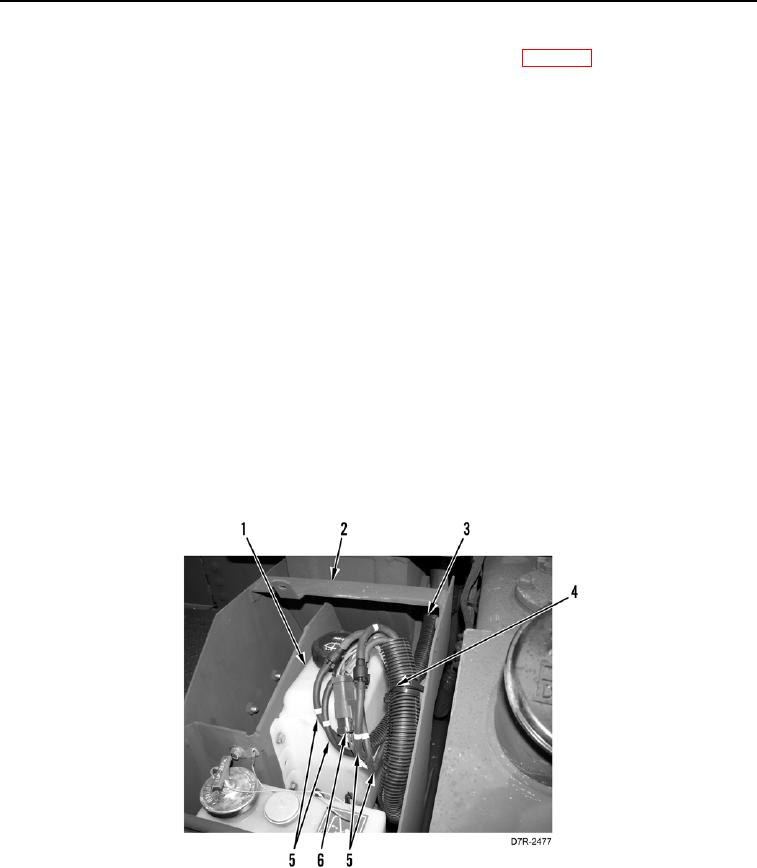
6. Route hose and harness conduit (Figure 6, Item 3) to pivot shaft oil reservoir compartment (Figure 6, Item 2).
7. Install new tiedown straps (Figure 6, Item 4) on hose and harness conduit (Figure 6, Item 3).
8. Connect cab wiring harness connector (Figure 6, Item 6) and four washer hoses (Figure 6, Item 5) to washer
bottle (Figure 6, Item 1).
Figure 6. Washer Electrical Harness and Hoses.
0226