
TM 5-2410-241-23-3
0247
ASSEMBLY CONTINUED
000247
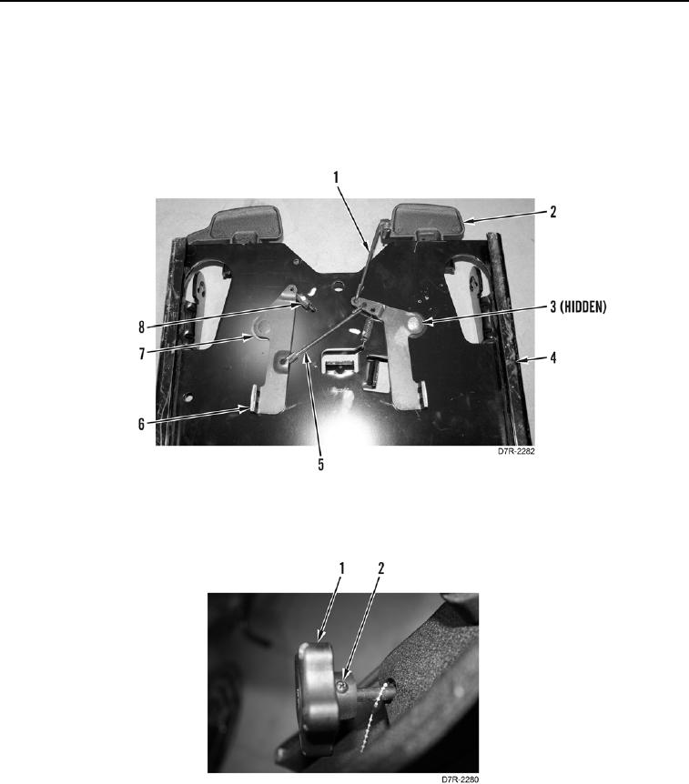
5. Install rod (Figure 22, Item 1) on seat adjuster release lever (Figure 22, Item 2).
6. Install rod (Figure 22, Item 5) on two parts of seat adjuster (Figure 22, Item 6).
7. Position two washers (Figure 22, Item 7) and seat adjuster (Figure 22, Item 6) on seat pan (Figure 22, Item 4)
and install two nuts (Figure 22, Item 3).
8. Install two springs (Figure 22, Item 8) on seat pan (Figure 22, Item 4) and seat adjuster (Figure 22, Item 6).
Figure 22. Seat Adjuster Springs.
0247
9. Position lumbar support adjustment knob (Figure 23, Item 1) on assembly and install screw (Figure 23, Item 2).
Figure 23. Lumbar Support Adjustment Knob.
0247