
TM 5-2410-241-23-3
0253
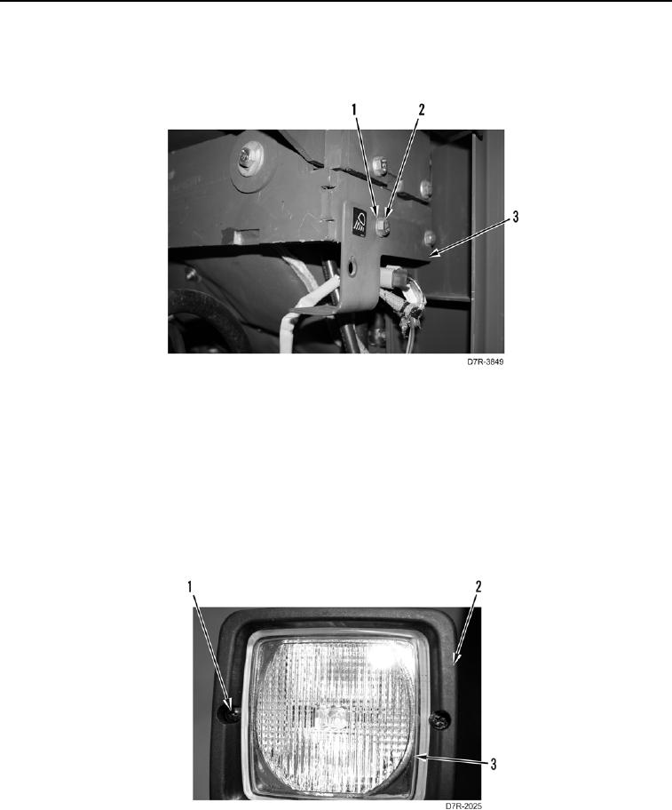
FLOOD LAMP SWITCH REMOVAL CONTINUED
4. Remove two bolts (Figure 7, Item 2), washers (Figure 7, Item 1), and mounting bracket (Figure 7, Item 3) from
machine.
Figure 7. Mounting Bracket.
0253
END OF TASK
FLOOD LAMP DISASSEMBLY
000253
N OT E
Flood lamp assembly does not have to be removed for this procedure.
1. Remove two screws (Figure 8, Item 1) and trim (Figure 8, Item 2) from flood lamp (Figure 8, Item 3).
Figure 8. Flood Lamp Screws and Trim.
0253