
TM 5-2410-241-23-3
0259
INSTALLATION CONTINUED
N OT E
Install electrical connector as tagged during removal.
5. Connect electrical connector (Figure 10, Item 1) and position pilot valve and hand control assembly (Figure 10,
Item 3) on plate (Figure 10, Item 2).
Figure 10. Electrical Connector.
0259
N OT E
Install hoses as tagged during removal.
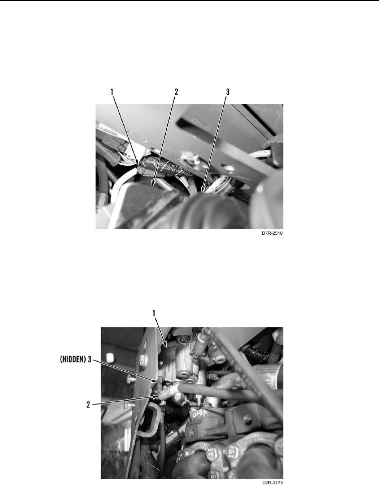
6. Install seven O-rings (Figure 11, Item 3) and hoses (Figure 11, Item 2) on pilot valve (Figure 11, Item 1).
Figure 11. Hoses and Pilot Valve.
0259