
TM 5-2410-240-10
0004
OPERATOR CONTROLS AND INDICATORS CONTINUED
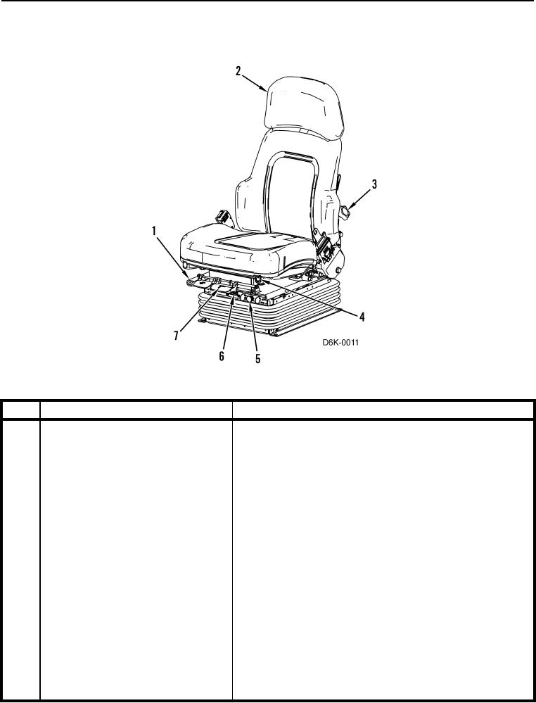
Air Suspension Seat
0004
Figure 4. Seat.
0004
KEY
COMPONENT
DESCRIPTION
1
Back Cushion Angle Adjustment Lever
Pull up on lever to release angle adjustment lock. Allow back
to spring forward or lean backward to adjust. Release lever to
lock.
2
Back Extension
Grasp back extension and pull up to remove.
3
Lumbar Support Knob
Rotate knob counterclockwise to increase stiffness of lumbar
support.
Rotate knob clockwise to decrease stiffness.
4
Seat Cushion Tilt
Front of seat cushion is pinned in a groove. Grasp seat pan
and rotate "forward-up-and-back" to position seat into a steep
angle.
Grasp seat pan and rotate "forward-down-and-back" to posi-
tion seat at nominal angle.
5
Seat Height Adjustment Knob
Push in knob to activate air pump to raise seat (engine start
switch must be in ON position). Pull knob to lower.
6
Ride Zone Indicator
Indicates if seat suspension is too high or too low. White bar in
green zone indicates proper seat height adjustment.
7
Forward/Back Seat Adjustment Lever
Pull up on lever to adjust seat forward or backward. Release
lever to lock.