
18
TM 5-2410-240-23-1
FIELD MAINTENANCE
-
THEORY OF OPERATION ENGINE
0
004
ENGINE SYSTEMS
0004
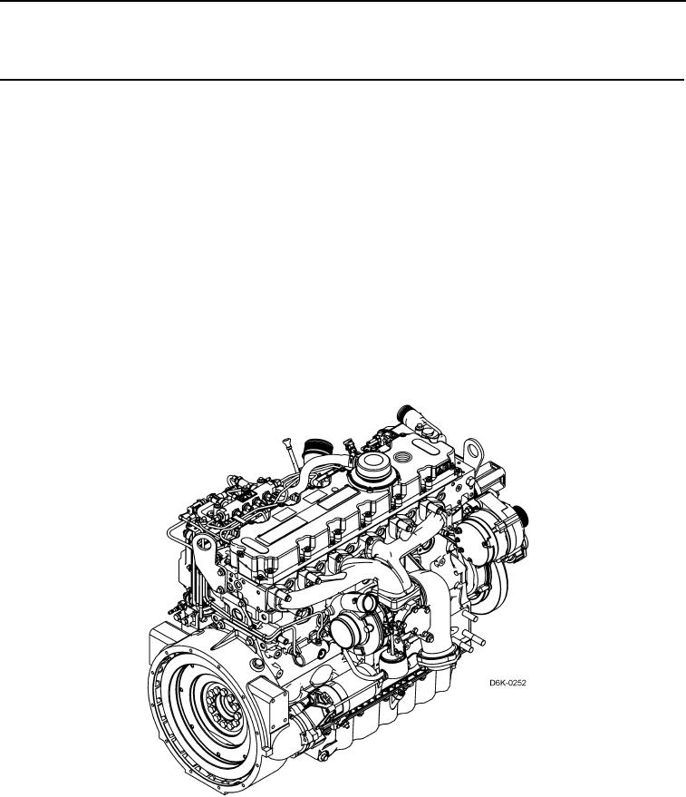
The engine delivers power to the hydrostatic piston pumps for hydraulic system operation. The 6.6 L, 4-cycle, in-
line 6-cylinder diesel engine:
is liquid-cooled.
has 24 valves.
is turbocharged and intercooled.
has a common rail fuel injection system.
has a pressure lubrication system. This system has an ol cooler and uses full flow filters. An engine oil sam-
i
pling valve is located on the engine oil filter base.
is controlled by the engine Electronic Control Module (E M). The engine ECM mounts on the left rear of the
C
engine.
runs on JP-8, or No. 1 or No. 2 diesel fuel.
develops a flywheel horsepo er of 125 hp at 2,100 rpm.
w
Figure 1. Engine Profile.
0004