
TM 5-2410-240-23-1
0004
ENGINE SYSTEMS CONTINUED
Engine Electronic Control Module (ECM)
0004
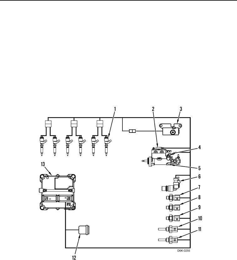
The engine ECM controls engine operating parameters based on inputs from various sensors. It also controls
engine operating parameters through software within the engine ECM. The parameters include all of the operating
maps and customer selected parameters.
The engine ECM functions as a governor and a computer for the fuel system. The engine ECM receives signals
from various sensors in order to control the timing and the engine speed.
The programmable software within the engine ECM contains all the fuel setting information. The information
determines engine performance. Flash programming is the method of programming or updating the programmable
software.
The engine ECM communicates with the machine ECM by means of the Controller Area Network (CAN) bus.
The engine ECM is sealed and needs no routine adjustment or maintenance. The engine ECM is the most reliable
component in the system. Most problems in the system will occur in the connectors or the wiring harness.
Therefore, the engine ECM should be the last item considered for replacement when making a diagnosis.
Figure 3. Engine ECM Inputs and Outputs.
0004