
TM 5-2410-240-23-1
0010
ELECTRO-HYDRAULIC CONTROLS CONTINUED
4. Neutral Continued
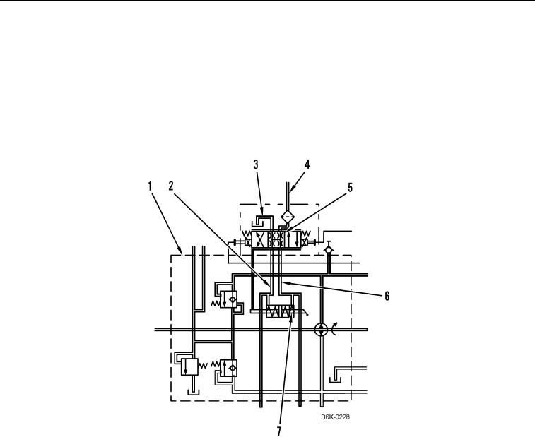
As a result of the duty cycle settings, the hydrostatic drive motors remain at the maximum displacements. At each
hydrostatic pump (Figure 8, Item 1), pilot oil flows from the line (Figure 8, Item 4) through the proportional solenoid
valve (Figure 8, Item 5) into the passage (Figure 8, Item 3) and to the case drain. The pressure in the passage
(Figure 8, Item 6) remains equal to the pressure in the passage (Figure 8, Item 2). The springs on each side of the
actuator piston (Figure 8, Item 7) center the piston, and the swashplate remains at a zero angle. Since the
swashplates in both pumps are at zero angles, both loops of the hydrostatic system are in a hydraulic lock and the
machine does not move.
Figure 8. Hydraulic Oil Flow for Neutral Operation.
0010