
TM 5-2410-240-23-1
0010
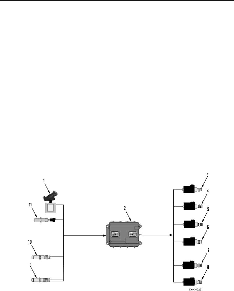
ELECTRO-HYDRAULIC CONTROLS CONTINUED
7. Left Pivot Turn
N OT E
The pivot turn is performed without brake engagement.
The machine ECM (Figure 13, Item 2) interprets two signals and determines that the joystick (Figure 13, Item 1) is
in the FORWARD and PIVOT LEFT position. The machine ECM sets the duty cycle for the motor displacement
control solenoid (Figure 13, Item 7) at less than 33% and the duty cycle for the motor displacement control
solenoid (Figure 13, Item 8) between 33% and 70%. These solenoids are located in the left and right hydrostatic
drive motors, respectively.
The machine ECM (Figure 13, Item 2) also sets the duty cycle for the reverse solenoid (Figure 13, Item 6) at less
than 23.5%, and the duty cycle for the forward solenoid (Figure 13, Item 4) between 26% and 88.5%. These
solenoids adjust the proportional solenoid valves in the right side hydrostatic pump.
The machine ECM (Figure 13, Item 2) also sets the duty cycle for the reverse solenoid (Figure 13, Item 5) at less
than 23.5% and the duty cycle for the forward solenoid (Figure 13, Item 3) at less then 26%. These solenoids
adjust the proportional solenoid valves in the left side hydrostatic pump.
N OT E
The duty cycles determine the angle of the pump and motor swashplates. The machine
ECM (Figure 13, Item 2) varies the duty cycles to the motor displacement solenoid
(Figure 13, Item 8) in the right hydrostatic drive motor, and to the forward solenoid
(Figure 13, Item 4) in the right side hydrostatic pump, based on signals received from the
travel speed switch in joystick (Figure 13, Item 1). The machine ECM also adjusts the duty
cycles based on signals received from the engine speed sensors (Figure 13, Item 11) and
motor speed sensors (Figure 13, Items 9 and 10) in order to prevent an overspeed,
underspeed, or stall condition, and to ensure the machine is tracking in a straight line.
Figure 13. Machine ECM Inputs and Outputs for Left Pivot Turn.
0010