
TM 5-2410-240-23-1
0010
ELECTRO-HYDRAULIC CONTROLS CONTINUED
9. Right Pivot Turn Continued
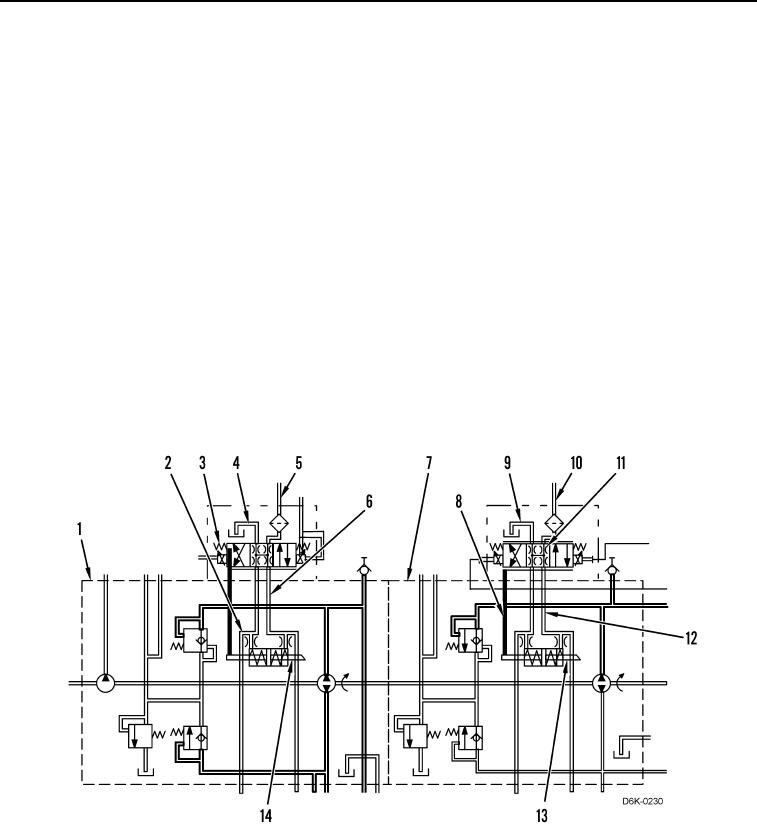
As a result of the duty cycle settings, the right hydrostatic drive motor remains at maximum displacement. For the
right side hydrostatic pump (Figure 18, Item 1), pilot oil flows from the line (Figure 18, Item 5) through the
proportional solenoid valve (Figure 18, Item 3) into the passage (Figure 18, Item 4) and to the case drain. The
pressure in the passage (Figure 18, Item 6) remains equal to the pressure in the passage (Figure 18, Item 2). The
springs on each side of the actuator piston (Figure 18, Item 14) center the piston, and the swashplate remains at a
zero angle.
Since the right side hydrostatic pump swashplate is at a zero angle, the right drive loop of the hydrostatic system is
in a hydraulic lock and the right track does not move.
In turn, inside the left hydrostatic pump (Figure 18, Item 7), the proportional solenoid valve (Figure 18, Item 11)
shifts to the left. Pilot oil flows from the line (Figure 18, Item 10) through the proportional solenoid valve into the
passage (Figure 18, Item 12) and then into the chamber of the actuator piston (Figure 18, Item 13). Inside the
chamber, the oil overcomes the force of the opposite spring and the actuator piston shifts to the left.
As the actuator piston (Figure 18, Item 13) shifts to the left, oil flows from the chamber of the actuator piston into
passage (Figure 18, Item 8) and then through the proportional solenoid valve (Figure 18, Item 11) and the passage
(Figure 18, Item 9) to the pump case drain.
As a result, the displacement of left side hydrostatic pump (Figure 18, Item 7) increases, and oil flows from the
pump to the left hydrostatic drive motor. As the oil flows through the motor, the motor rotates. In turn, the left track
moves forward, and the machine turns to the right while pivoting on the right track.
Figure 18. Hydraulic Oil Flow for Right Pivot Turn.
0010