
TM 5-2410-240-23-1
0010
ELECTRO-HYDRAULIC CONTROLS CONTINUED
8. Left Counterrotate Turn Continued
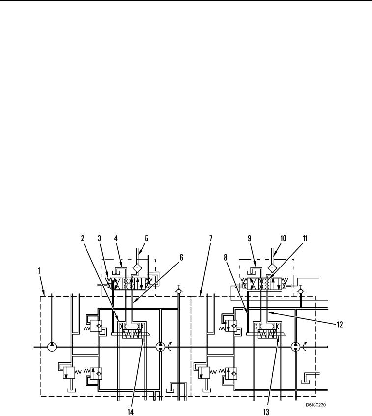
As a result of the duty cycle settings, inside the left side hydrostatic pump (Figure 16, Item 7), the proportional
solenoid valve (Figure 16, Item 11) shifts to the right. Pilot oil flows from the line (Figure 16, Item 10) through the
proportional solenoid valve into the passage (Figure 16, Item 8) and then into the chamber of the actuator piston
(Figure 16, Item 13). Inside the chamber, the oil overcomes the force of the opposite spring and the actuator piston
shifts to the right.
As the actuator piston (Figure 16, Item 13) shifts to the right, oil flows from the chamber of the actuator piston to the
passage (Figure 16, Item 12), and then through the proportional solenoid valve (Figure 16, Item 11) and the
passage (Figure 16, Item 9) to the pump case drain.
Inside the right hydrostatic pump (Figure 16, Item 1), the proportional solenoid valve (Figure 16, Item 3) shifts to the
left. Pilot oil flows from the line (Figure 16, Item 5) through the proportional solenoid valve into the passage
(Figure 16, Item 6) and then into the chamber of the actuator piston (Figure 16, Item 14). Inside the chamber, the
oil overcomes the force of the opposite spring and the actuator piston shifts to the left.
As the actuator piston (Figure 16, Item 14) shifts to the left, oil flows from the chamber of the actuator piston to the
passage (Figure 16, Item 2) and then through the proportional solenoid valve (Figure 16, Item 3) and the passage
(Figure 16, Item 4) to the pump case drain.
As a result, the displacements of left and right side hydrostatic pumps (Figure 16, Items 7 and 1) increase, and oil
flows from the pumps to the left and the right hydrostatic drive motor, respectively. As the oil flows through the
motors, the motors rotate. In turn, the left track rotates backward, the right track rotates forward, and the machine
rotates counterclockwise through the center axis of the machine.
Figure 16. Hydraulic Oil Flow for Left Counterrotate Turn.
0010