
TM 5-2410-240-23-1
0011
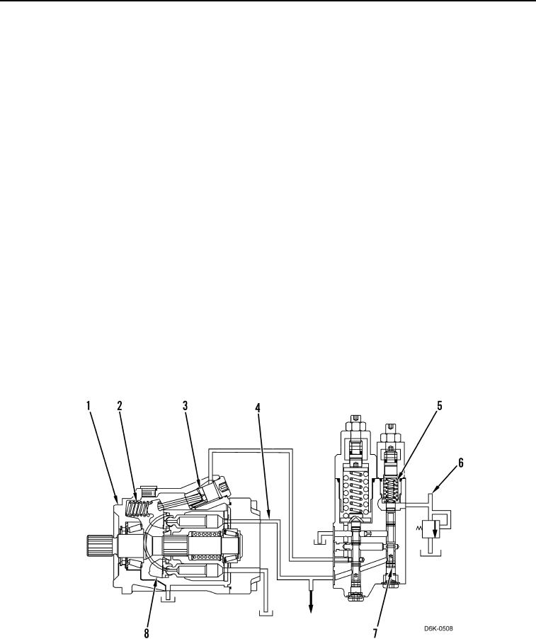
IMPLEMENT HYDRAULIC SYSTEM CONTINUED
3. Destroke
When the system requires less flow, the implement pump (Figure 5, Item 1) destrokes. The implement pump
destrokes when supply pressure from the pump outlet (Figure 5, Item 4) becomes greater than the load sensing
(signal) oil pressure (Figure 5, Item 6), the boost pressure, and the margin spring pressure (Figure 5, Item 5)
combined. In turn, the flow compensator (margin) spool (Figure 5, Item 7) rises, which allows more oil flow to the
actuator piston (Figure 5, Item 3). The increased pressure on the actuator piston overcomes the force of the bias
spring (Figure 5, Item 2), which moves the swashplate (Figure 5, Item 8) to a reduced angle.
When supply pressure at the pump outlet (Figure 5, Item 4) matches the combined load sensing (signal) oil
pressure (Figure 5, Item 6), boost pressure, and margin spring pressure (Figure 5, Item 5), then the flow
compensator (margin) spool (Figure 5, Item 7) returns to a metering position, and the piston pump (Figure 5,
Item 1) returns to a constant flow.
The following conditions result in destroking the implement pump (Figure 5, Item 1):
When a main control spool for a hydraulic control valve moves to the HOLD position.
If the main control spool for a hydraulic contro valve moves to a position that requires less flow.
l
If multiple hydraulic control valves are in use and there is a reduction inflow demand from any one of the
hydraulic control valves.
If the engine speed increases.
When the implement pump (Figure 5, Item 1) destrokes, supply oil pressure from the pump outlet (Figure 5, Item 4)
decreases on the bottom side of the flow compensator (margin) spool (Figure 5, Item 7). The force on the top of the
flow compensator (margin) spool is the sum of pressure from the margin spring (Figure 5, Item 5), the load sensing
(signal) oil pressure (Figure 5, Item 6), and the boost pressure. Supply pressure at the pump outlet acts on the
bottom of the flow compensator (margin) spool. Once the forces become equal on each end of the spool, the flow
compensator (margin) spool will meter oil to the actuator piston (Figure 5, Item 3) and the system stabilizes. The
system will provide a constant flow until the flow requirements change.
Figure 5. Destroke.
0011