
TM 5-2410-240-23-1
0011
IMPLEMENT HYDRAULIC SYSTEM CONTINUED
4. High Pressure Stall
N OT E
This condition will only occur when the load sensing relief valve (Figure 6, Item 5) is set
below the value of the pressure compensator.
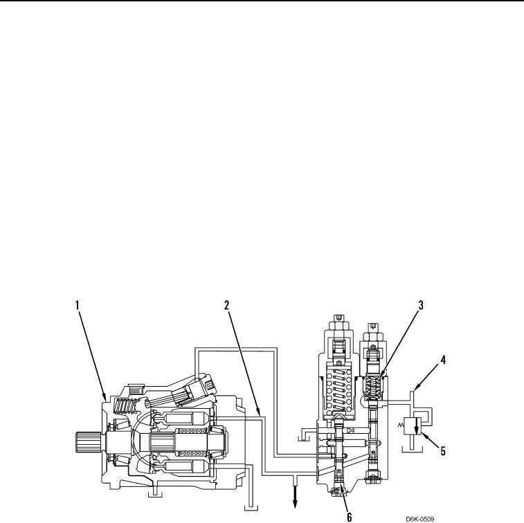
If the implement pump (Figure 6, Item 1) is at a high pressure stall or maximum system pressure, then the
combined load sensing (signal) oil pressure (Figure 6, Item 4), boost pressure, and margin spring pressure
(Figure 6, Item 3) is equal to the supply pressure at pump outlet (Figure 6, Item 2).
The load sensing relief valve (Figure 6, Item 5) limits the maximum system pressure at any pump displacement. If
the adjustment of the load sensing relief valve is incorrect, the pressure compensator spool (Figure 6, Item 6)
serves as a backup relief in order to protect the hydraulic system. The pressure compensator spool also controls
pressure spikes within the hydraulic system.
At high pressure stall, the implement pump (Figure 6, Item 1) is at minimum flow and supply oil at the pump outlet
(Figure 6, Item 2) is at maximum pressure. These conditions are maintained for a single implement in a stall
condition. However, if multiple implement hydraulic circuits activate and one circuit is at a stall, the implement
pump will upstroke in order to meet the increased flow demands. This flow meets the needs of the other circuits
that are operating at a lower work port pressure.
Figure 6. High Pressure Stall.
0011