
TM 5-2410-240-23-2
0044
DISASSEMBLY
00044
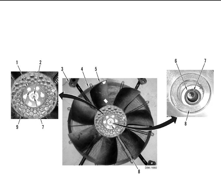
1. Remove six bolts (Figure 8, Item 1), washers (Figure 8, Item 9), and spider (Figure 8, Item 5) from hub
(Figure 8, Item 8).
2. Remove guard (Figure 8, Item 4) from fan support (Figure 8, Item 3).
3. Remove nut (Figure 8, Item 2) and lockwasher (Figure 8, Item 6) retaining hub (Figure 8, Item 8) on shaft
(Figure 8, Item 7). Discard lockwasher.
4. Using a puller, remove hub (Figure 8, Item 8) from shaft (Figure 8, Item 7).
Figure 8. Spider, Guard, Hub, and Retaining Hardware.
0044