
TM 5-2410-240-23-2
0106
REMOVAL
000106
WARN I N G
Hydraulic oil is very slippery. Immediately wipe up any spills. Failure to follow this warning
may result in injury to personnel.
N OT E
Mark position and routing of hoses for installation.
Cap hydraulic lines and fittings.
The following procedure is for one diagnostic hose. Use the same procedure for each
additional diagnostic hose.
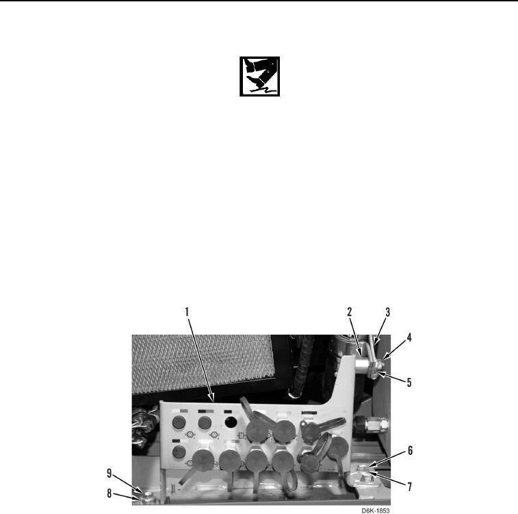
1. Remove nut (Figure 1, Item 4), washer (Figure 1, Item 5), clamp (Figure 1, Item 3), and spacer (Figure 1,
Item 2) from bulkhead bracket (Figure 1, Item 1).
2. Remove two bolts (Figure 1, Item 6) and washers (Figure 1, Item 7) from bulkhead bracket (Figure 1, Item 1).
3. Remove bolt (Figure 1, Item 9) and spacer (Figure 1, Item 8) from bulkhead bracket (Figure 1, Item 1). Move
bulkhead bracket aside.
Figure 1. Hydraulic Diagnostic Center.
0106