
TM 5-2410-240-23-3
0175
INSTALLATION
000175
WARN I N G
Use extreme caution when handling heavy parts. Provide adequate support and use
assistance during procedure. Failure to follow this warning may result in death or injury to
personnel.
N OT E
Fuel tank weighs approximately 76 lb (35 kg).
Install electrical connectors as noted during removal.
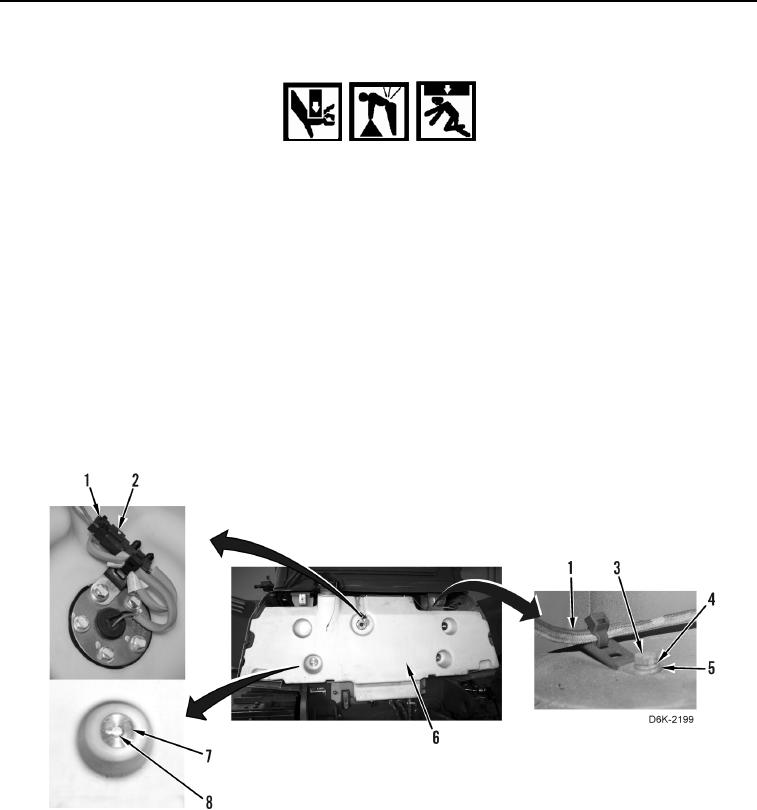
1. With assistance, install fuel tank (Figure 21, Item 6) on machine.
2. Install four spacers (Figure 21, Item 7) and bolts (Figure 21, Item 8) retaining fuel tank (Figure 21, Item 6) on
machine.
3. Position chassis harness (Figure 21, Item 1) on fuel tank (Figure 21, Item 6).
4. Install three clips (Figure 21, Item 5), washers (Figure 21, Item 4), and bolts (Figure 21, Item 3) on fuel tank
(Figure 21, Item 6).
5. Connect chassis harness (Figure 21, Item 1) to fuel level sender harness (Figure 21, Item 2).
Figure 21. Fuel Level Sender, Chassis Harness, Fuel Tank, and Retaining Hardware.
0175