
6
TM 5-2410-240-23-3
FIELD MAINTENANCE
-
LEFT REAR ACCESS DOOR REPLACEMENT
01
92
Door Latch Assembly and Striker Plate Removal, Left Rear Access Door Removal,
Cleaning and Inspection, Left Rear Access Door Installation,
Door Latch Assembly and Striker Plate Installation
INITIAL SETUP
Equipment Conditions
Tools and Special Tools
0
0
Tool Kit, General Mechanic's
Machine parked (TM 5-2410-240-10)
0
(WP 0289, Item 51)
0
Drawings Required
0
Materials/Parts
TM 5-2410-240-24P, Figure 85
0
0
Rag, wiping (WP 0290, Item 21)
0
Estimated Time to Complete
0
References
1.0 Hr
0
0
0
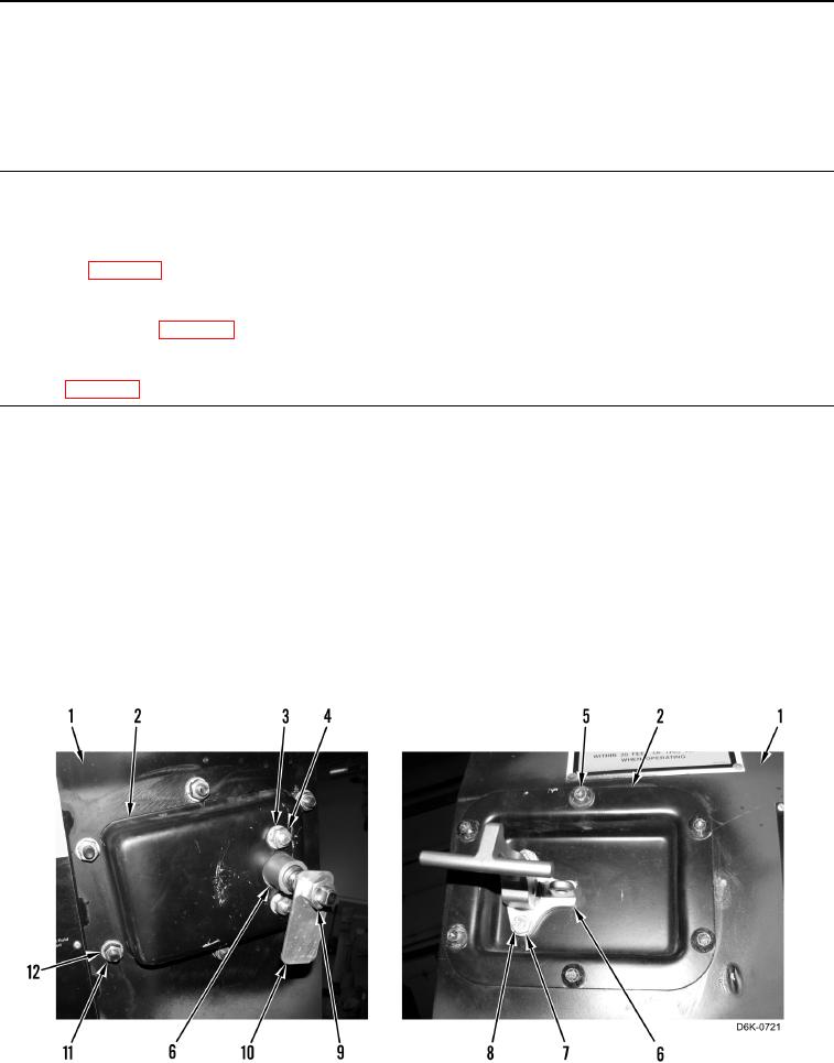
DOOR LATCH ASSEMBLY AND STRIKER PLATE REMOVAL
000192
1. Open left rear access door (Figure 1, Item 1).
N OT E
Note position of latch plate in relation to the handle to aid assembly.
2. Remove nut (Figure 1, Item 9) and latch plate (Figure 1, Item 10) from latch assembly (Figure 1, Item 6).
3. Remove two nuts (Figure 1, Item 4), washers (Figure 1, Item 3), bolts (Figure 1, Item 8), washers (Figure 1,
Item 7), and latch assembly (Figure 1, Item 6) from door plate (Figure 1, Item 2).
4. Remove six nuts (Figure 1, Item 11), washers (Figure 1, Item 12), bolts (Figure 1, Item 5), and door plate
(Figure 1, Item 2) from door (Figure 1, Item 1).
Figure 1. Door Latch Assembly.
0192