
TM 5-2410-240-23-3
0190
INSTALLATION CONTINUED
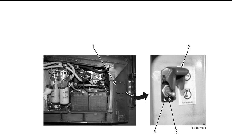
19. Install guard (Figure 18, Item 2) and nut (Figure 18, Item 4) on lockout switch (Figure 18, Item 3).
20. Position guard (Figure 18, Item 2) downward.
21. Close lockout switch access door (Figure 18, Item 1).
Figure 18. Lockout Switch and Guard.
0190
END OF TASK
FOLLOW-ON TASKS
000190
1. Install outer battery tray (WP 0142).
2. Verify correct operation of machine (TM 5-2410-240-10).
END OF TASK
END OF WORK PACKAGE
0190-13/(14 blank)