
TM 5-2410-240-23-3
0194
CLEANING AND INSPECTION
000194
Clean and inspect all components IAW Mechanical General Maintenance Instructions (WP 0282).
END OF TASK
FUEL TANK GUARD INSTALLATION
000194
WARN I N G
Use extreme caution when handling heavy parts. Provide adequate support and use
assistance during procedure. Ensure that any lifting equipment used is in good condition
and of suitable load capacity. Keep clear of heavy parts supported by lifting equipment.
Failure to follow this warning may result in death or injury to personnel.
N OT E
Fuel tank guard weighs approximately 385 lb (175 kg).
1. Install lifting device on fuel tank guard (Figure 9, Item 2).
2. Using lifting device and with assistance, install fuel tank guard (Figure 9, Item 2) on machine (Figure 9, Item 3).
3. Install four washers (Figure 9, Item 1) and bolts (Figure 9, Item 4) on fuel tank guard (Figure 9, Item 2) on
machine (Figure 9, Item 3).
4. Remove lifting device from fuel tank guard (Figure 9, Item 2).
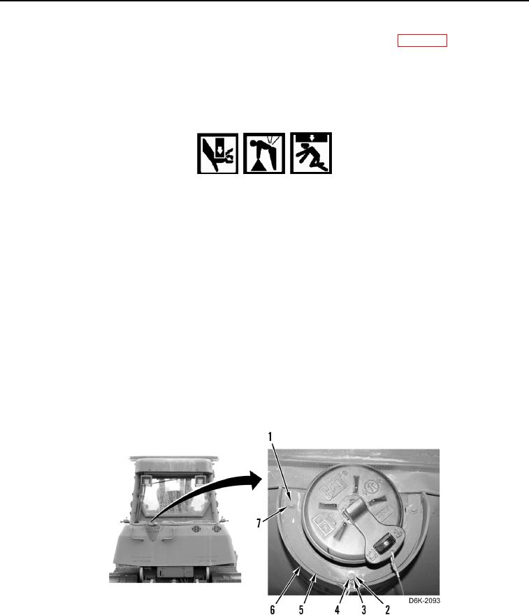
5. Install plate (Figure 10, Item 5), washer (Figure 10, Item 2), chain (Figure 10, Item 4), and bolt (Figure 10,
Item 3) on fuel tank guard (Figure 10, Item 6).
6. Install two washers (Figure 10, Item 7) and bolts (Figure 10, Item 1) on fuel tank guard (Figure 10, Item 6).
Figure 10. Retaining Hardware on Rear of Machine.
0194