
TM 5-2410-240-23-3
0212
RIGHT SIDE CONSOLE INSTALLATION CONTINUED
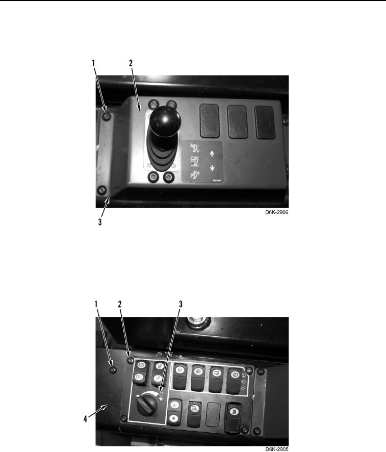
8. Install rear control panel (Figure 25, Item 2), and four screws (Figure 25, Item 1) on console (Figure 25,
Item 3).
Figure 25. Control Panel - Rear.
0212
9. Install front control panel (Figure 26, Item 3) on right side console (Figure 26, Item 4) with four screws
(Figure 26, Item 2).
10. Secure right side console (Figure 26, Item 4) with three screws (Figure 26, Item 1)
Figure 26. Control Panel - Front.
0212
END OF TASK