
TM 5-2410-240-23-3
0212
RIGHT SIDE CONSOLE INSTALLATION
000212
1. Connect harness connector (Figure 22, Item 1) to messenger (Figure 22, Item 2) and position right side
console (Figure 22, Item 3) in cab.
Figure 22. Right Console.
0212
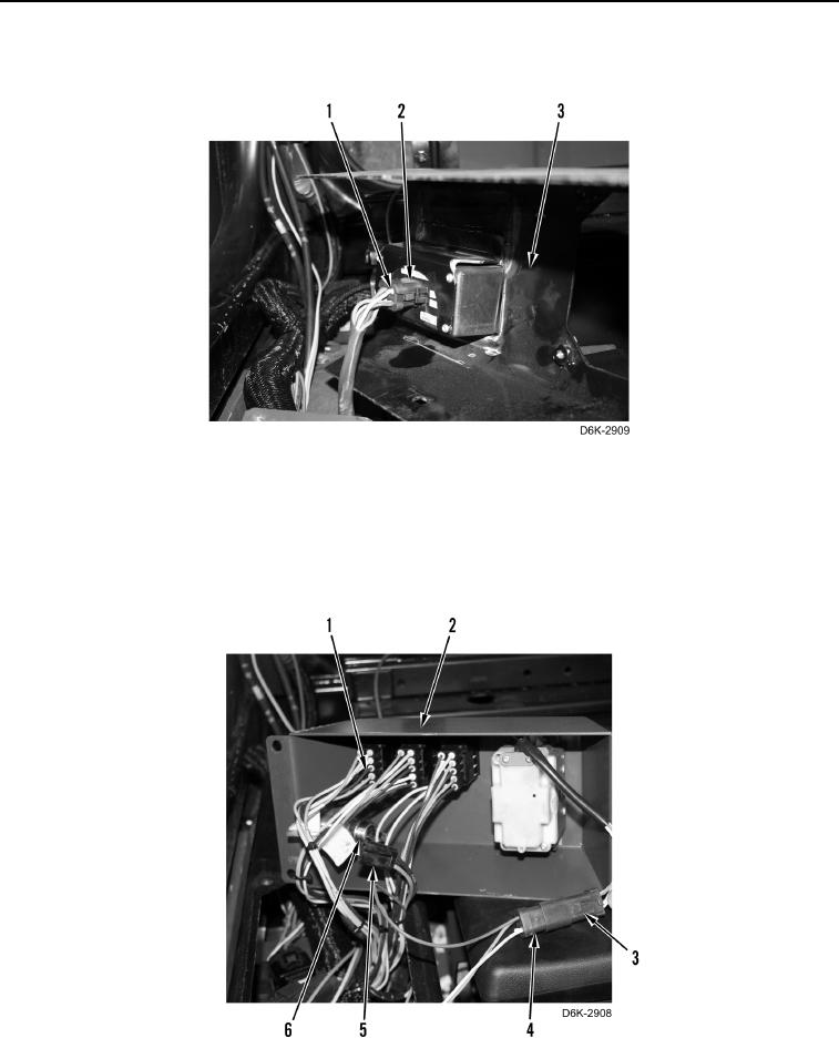
2. Install 12V accessory receptacle (Figure 23, Item 6) on control panel (Figure 23, Item 2).
3. Connect 12V harness connector (Figure 23, Item 5) to 12V accessory receptacle (Figure 23, Item 6).
4. Connect ripper control harness connector (Figure 23, Item 3) to main harness connector (Figure 23, Item 4).
5. Connect three winch control harness connectors (Figure 23, Item 1) to control panel (Figure 23, Item 2).
Figure 23. Right Console.
0212