
TM 5-2410-240-23-3
0225
REMOVAL CONTINUED
N OT E
Tag hoses and note routing to aid installation.
Note location and quantity of tiedown straps to aid installation.
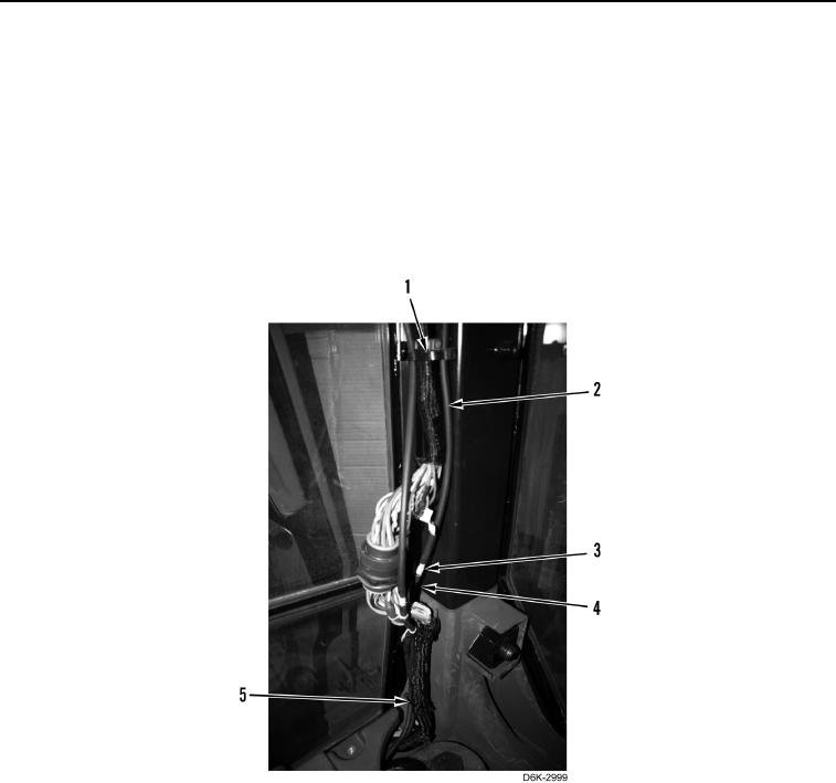
6. Remove tiedown strap (Figure 3, Item 1) and upper hose (Figure 3, Item 2) from cab. Discard tiedown strap.
7. Remove upper hose (Figure 3, Item 2) from connector (Figure 3, Item 3) and remove upper hose from cab.
8. Remove two tiedown straps (Figure 3, Item 5) from lower hose (Figure 3, Item 4). Discard tiedown straps.
9. Disconnect lower hose (Figure 3, Item 4) from connector (Figure 3, Item 3).
Figure 3. Rear Hose Routing on Rear Pillar.
0225