
TM 5-2410-240-23-3
0235
DISASSEMBLY CONTINUED
000235
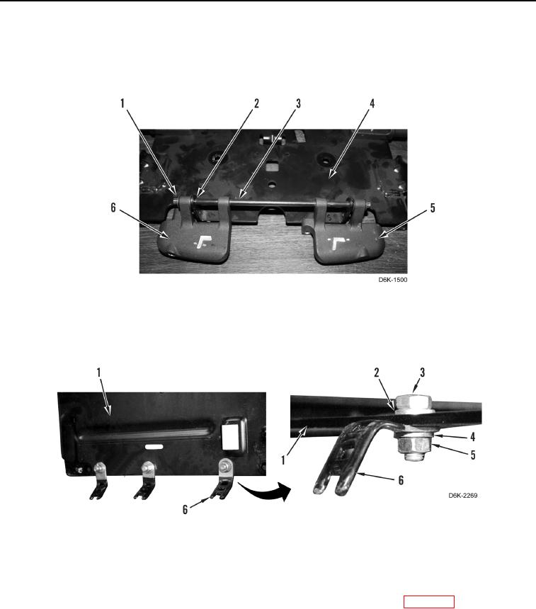
23. Remove two retainers (Figure 18, Item 1) from rod (Figure 18, Item 3). Discard retainers.
24. Remove rod (Figure 18, Item 3), four washers (Figure 18, Item 2), seat adjuster release lever (Figure 18,
Item 5), and seat recliner lever (Figure 18, Item 6) from seat adjuster (Figure 18, Item 4).
Figure 18. Seat Levers.
0235
25. Remove three nuts (Figure 19, Item 5), washers (Figure 19, Item 4), clips (Figure 19, Item 6), washers
(Figure 19, Item 2), and bolts (Figure 19, Item 3) from seat adjuster (Figure 19, Item 1).
Figure 19. Nuts, Bolts, and Clips.
0235
END OF TASK
CLEANING AND INSPECTION
000235
Clean and inspect all components IAW Mechanical General Maintenance Instructions (WP 0282).
END OF TASK