• Home
  • Download PDF
  • Order CD-ROM
  • Order in Print
Figure 3. Joystick Harness Connectors.
Figure 5. Joystick Control Support Cover.

Field Maintenance Manual 3 D6K Dozer Type I With Winch and Type II With Ripper
Page Navigation
  660    661    662    663    664  665  666    667    668    669    670  
img
.
TM 5-2410-240-23-3
0238
REMOVAL CONTINUED
000238
N OT E
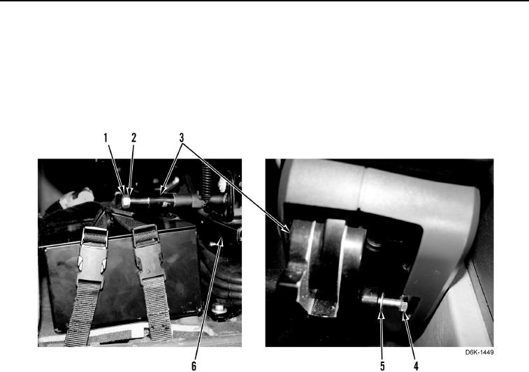
Move seat forward to access joystick control support assembly mounting bolts.
7. Remove four bolts (Figure 4, Items 1 and 4), washers (Figure 4, Items 2 and 5), and joystick control support
assembly (Figure 4, Item 3) from seat (Figure 4, Item 6).
Figure 4. Joystick Control Support Assembly Mounting Bolts.
0238
END OF TASK
0238-4


Privacy Statement
Press Release
Contact

© Copyright Integrated Publishing, Inc.. All Rights Reserved.