
TM 5-2410-240-23-3
0237
INSTALLATION CONTINUED
000237
N OT E
Install wiring harness as noted during removal.
Install tiedown straps as noted during removal.
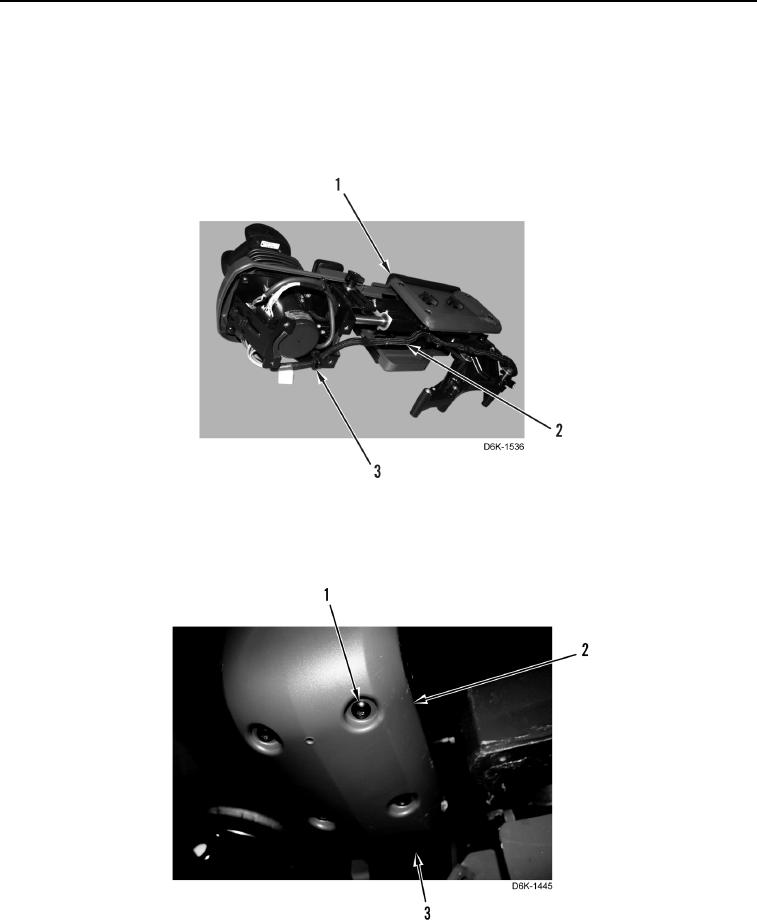
41. Install wiring harness (Figure 44, Item 2) and four new tiedown straps (Figure 44, Item 3) on joystick control
support assembly (Figure 44, Item 1).
Figure 44. Wiring Harness Tiedown Straps.
0237
42. Extend joystick control assembly. Install cover (Figure 45, Item 2) and four screws (Figure 45, Item 1) on
joystick control support assembly (Figure 45, Item 3).
Figure 45. Joystick Cover - Lower.
0237
END OF TASK