
TM 5-2410-240-23-3
0237
ASSEMBLY CONTINUED
000237
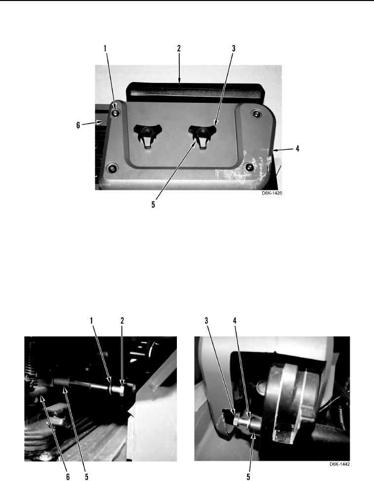
36. Install cover (Figure 40, Item 4), arm rest (Figure 40, Item 2), two washers (Figure 40, Item 5), adjustment
knobs (Figure 40, Item 3), and four screws (Figure 40, Item 1) on support (Figure 40, Item 6).
Figure 40. Joystick Control Support Cover.
0237
END OF TASK
INSTALLATION
000237
N OT E
Move seat forward to access joystick control support assembly mounting bolts.
37. Install joystick control support assembly (Figure 41, Item 5), four washers (Figure 41, Items 1 and 4), bolts
(Figure 41, Items 2 and 3) on seat (Figure 41, Item 6).
Figure 41. Joystick Control Support Assembly Mounting Bolts.
0237