
TM 5-2410-240-23-3
0237
ASSEMBLY CONTINUED
000237
26. Install bracket (Figure 30, Item 2) and bolt (Figure 30, Item 1) on support (Figure 30, Item 3).
Figure 30. Joystick Adjustment Lever and Bolt.
0237
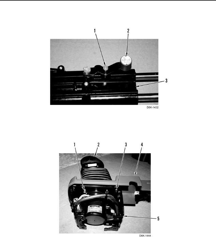
27. Install cover (Figure 31, Item 4), four screws (Figure 31, Item 3), joystick control assembly (Figure 31, Item 2)
and four bolts (Figure 31, Item 1) on bracket (Figure 31, Item 5).
Figure 31. Joystick Control Assembly, Cover, and Bracket.
0237