
TM 5-2410-240-23-3
0237
ASSEMBLY CONTINUED
000237
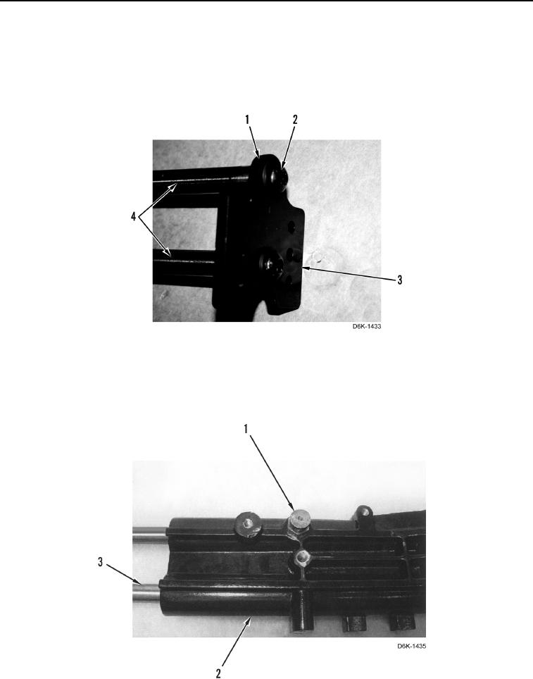
N OT E
Install bracket as noted during removal.
24. Install bracket (Figure 28, Item 3), two washers (Figure 28, Item 1), and screws (Figure 28, Item 2) on
adjustment rods (Figure 28, Item 4).
Figure 28. Joystick Control Mounting Plate.
0237
N OT E
Install adjustment rods as noted during removal.
25. Install adjustment rods (Figure 29, Item 3) and pin (Figure 29, Item 1) on support (Figure 29, Item 2).
Figure 29. Adjustment Rods and Pin.
0237