
TM 5-2410-240-23-3
0237
ASSEMBLY CONTINUED
000237
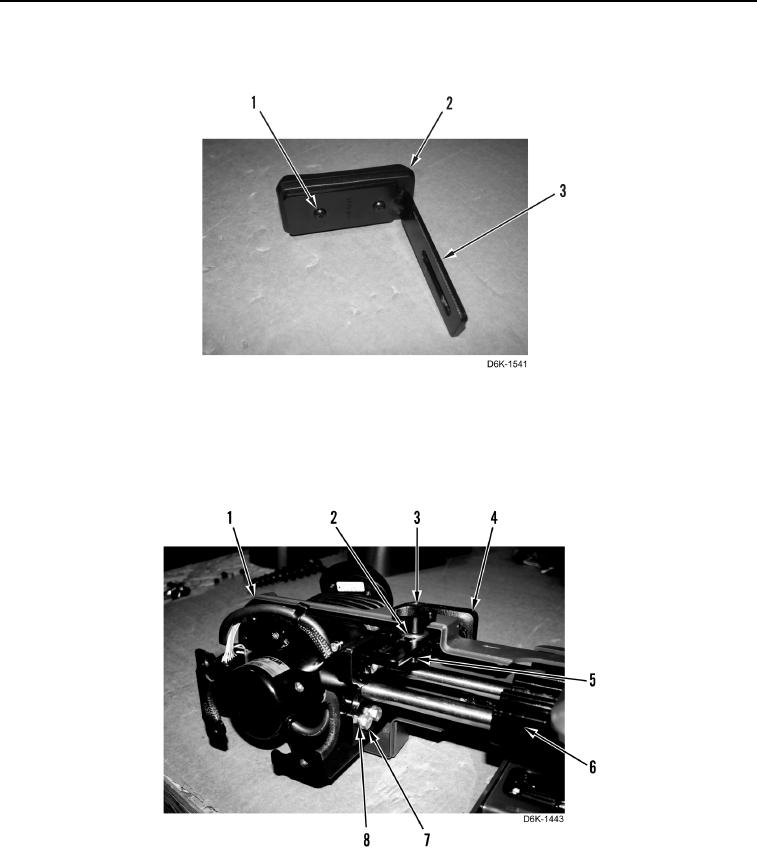
28. Install wrist pad cushion (Figure 32, Item 2) and two screws (Figure 32, Item 1) on bracket (Figure 32, Item 3).
Figure 32. Joystick Control Support Wrist Pad.
0237
29. Install joystick control support assembly (Figure 33, Item 1), bracket (Figure 33, Item 5), four washers
(Figure 33, Item 8), bolts (Figure 33, Item 7), wrist pad (Figure 33, Item 4), washer (Figure 33, Item 2), and
adjustment knob (Figure 33, Item 3) on support (Figure 33, Item 6).
Figure 33. Joystick Control Support Assembly, Bracket, and Bolts.
0237