
TM 5-2410-240-23-3
0237
INSTALLATION CONTINUED
000237
N OT E
Install electrical connectors as tagged during removal.
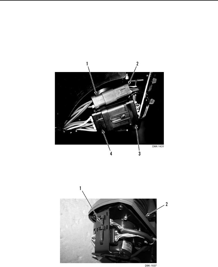
38. Connect horn/speed control connector (Figure 42, Item 4) on main harness connector (Figure 42, Item 3).
39. Connect steering/transmission control connector (Figure 42, Item 1) on main harness connector (Figure 42,
Item 2).
Figure 42. Joystick Harness Connectors.
0237
40. Install two new tiedown straps (Figure 43, Item 1) on joystick control support assembly (Figure 43, Item 2).
Figure 43. Joystick Connector Tiedown Straps.
0237