
TM 5-2410-240-23-3
0255
ASSEMBLY CONTINUED
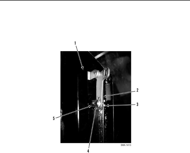
13. Inspect position of bellcrank assembly. Long leg of bellcrank (Figure 28, Item 2) should be parallel with door
(Figure 28, Item 1). Adjust position of bellcrank by removing latch rod retaining clip (Figure 28, Item 3) and pin
(Figure 28, Item 4). Remove bellcrank (Figure 28, Item 2) and turn clevis (Figure 28, Item 5) in or out. Install
bellcrank (Figure 28, Item 2), pin (Figure 28, Item 4), and retaining clip (Figure 28, Item 3), and inspect long leg
of bellcrank for parallelism on door (Figure 28, Item 1).
Figure 28. Door Handle Adjustment.
0255