
TM 5-2410-241-23-1
0004
ENGINE CONTINUED
Pistons, Rings, and Connecting Rods
0004
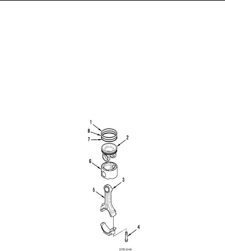
The piston is a two-piece articulated assembly. The piston has a forged steel crown (Figure 2, Item 2) and a forged
aluminum skirt (Figure 2, Item 6). Both parts are retained by the piston pin to the small end of the connecting rod.
Each piston has three rings:
Compression ring
Intermediate ring
Oil ring
Rings (Figure 2, Item 1, 7, and 8) are located in grooves in steel crown (Figure 2, Item 2). The rings seal the
crankcase from the combustion gases and provide control of the engine oil. The design of compression ring
(Figure 2, Item 1) is a barrel face with a plasma face coating. The design of intermediate ring (Figure 2, Item 8) is a
tapered shape and a chrome finish. Oil ring (Figure 2, Item 7) is double railed with a coil spring expander and has a
ground profile and a chrome finish.
Connecting rod (Figure 2, Item 5) is a conventional design. The cap is fastened to the rod by two bolts (Figure 2,
Item 4) that are threaded into the rod. Each side of the small end of the connecting rod (Figure 2, Item 3) is
machined at an angle of 12 degrees in order to fit within the piston cavity. This allows a larger surface area on the
piston, and connecting rod in order to minimize bearing load.
Figure 2. Piston, Rings, Connecting Rods.
0004