
TM 5-2410-241-23-1
0007
COOLING SYSTEM CONTINUED
Supply Manifold
0007
Cooling is provided for only the portion of the cylinder liner above the seal in the block. The antifreeze coolant
solution enters the block at each cylinder through the slits in the supply manifold. The supply manifold is an integral
casting in the block. The coolant flows around the circumference of the cylinder liner and into the cylinder head
through a single drilled passage for each liner. The coolant flow is split at each liner so that 60 percent flows
around the liner and the remainder bypasses the liner and flows directly to the cylinder head.
Aftercooler Flow
0007
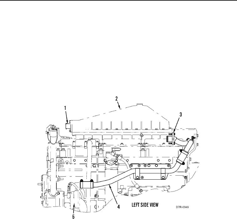
The gear driven aftercooler water pump (Figure 2, Item 5) is located on the left side of the engine. Coolant flows
from the aftercooler water pump through the cooler line (Figure 2, Item 4) into the aftercooler inlet (Figure 2,
Item 3). Coolant passes through the aftercooler (Figure 2, Item 2) to cool the turbocharger inlet air before it enters
the engine. Coolant exits the aftercooler outlet (Figure 2, Item 1) and returns to the radiator.
Figure 2. Aftercooler Flow.
0007
END OF WORK PACKAGE