
TM 5-2410-241-23-1
0011
IMPLEMENT AND STEERING HYDRAULIC SYSTEM CONTINUED
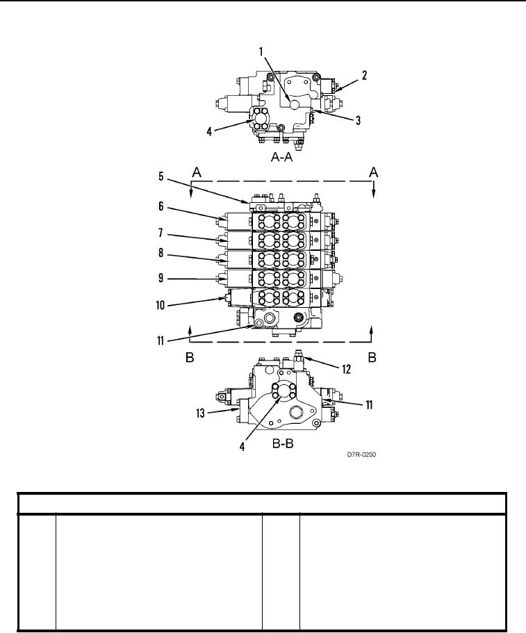
Figure 22. Implement Control Valves.
0011
Key Component
1
Identification Plate
8
Bulldozer Tilt Control Valve
2
Float Boost Signal
9
Bulldozer Lift Control Valve
3
Housing (Drain)
10
Steering Control Valve
4
Drain to Tank
11
Signal to Pump
5
Cover
12
Main Relief Valve
6
Ripper Tilt Control Valve
13
Pump Supply
7
Ripper Lift Control Valve