
TM 5-2410-241-23-1
0043
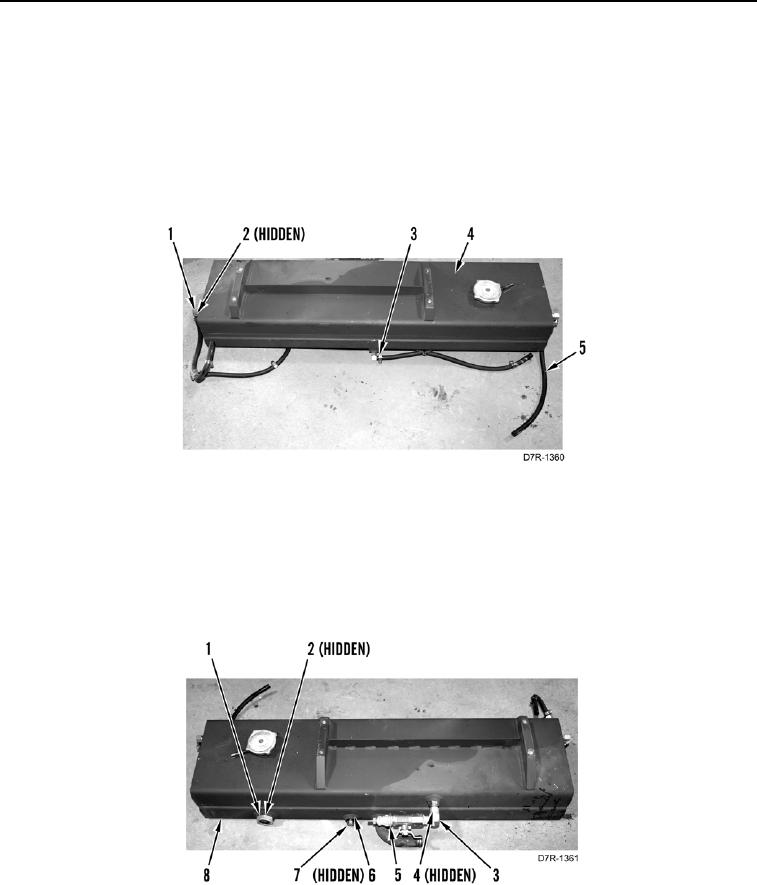
INSTALLATION CONTINUED
N OT E
Install hoses as tagged during removal.
2. Install three new O-rings (Figure 9, Item 2) and fittings (Figure 9, Item 1) on coolant tank (Figure 9, Item 4).
3. Install three clamps (Figure 9, Item 3) on hoses (Figure 9, Item 5).
4. Install three hoses (Figure 9, Item 5) on fittings (Figure 9, Item 1), tighten three clamps (Figure 9, Item 3).
Figure 9. Fittings.
0043
5. Install new O-ring (Figure 10, Item 4) and fitting (Figure 10, Item 3) on coolant tank (Figure 10, Item 8).
6. Install shutoff valve (Figure 10, Item 5) on fitting (Figure 10, Item 3).
7. Install new O-ring (Figure 10, Item 6) and plug (Figure 10, Item 7) on coolant tank (Figure 10, Item 8).
8. Install new O-ring (Figure 10, Item 2) and sight gauge (Figure 10, Item 1) on coolant tank (Figure 10, Item 8).
Figure 10. Sight Gauge.
0043