
TM 5-2410-241-23-2
0059
REMOVAL CONTINUED
N OT E
Tag hoses to aid installation.
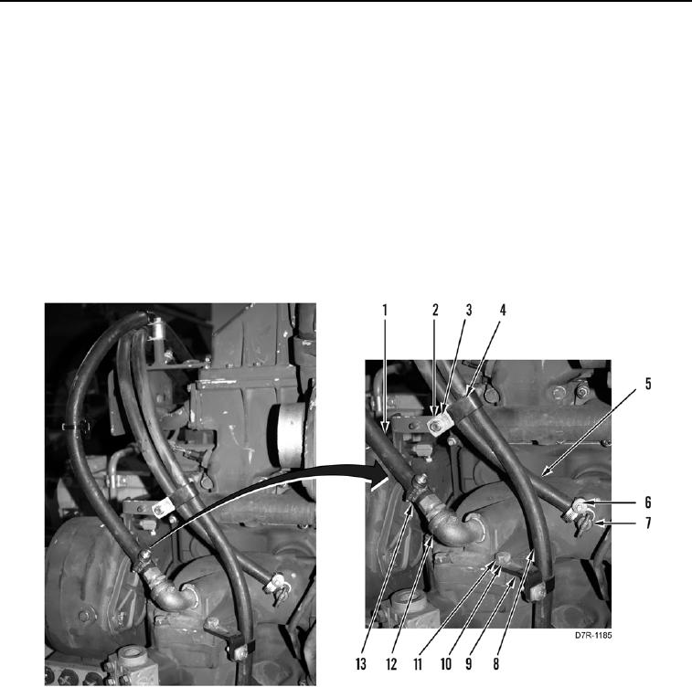
33. Remove nut (Figure 9, Item 2), washer (Figure 9, Item 3), and P-clip (Figure 9, Item 4) from two hoses
(Figure 9, Items 8 and 5).
34. Remove bolt (Figure 9, Item 11), washer (Figure 9, Item 10) and bracket (Figure 9, Item 9) from engine.
Position hose (Figure 9, Item 8) and bracket aside.
35. Loosen clamp (Figure 9, Item 13) and remove hose (Figure 9, Item 1) from fitting (Figure 9, Item 12). Position
hose aside.
36. Loosen clamp (Figure 9, Item 6) and remove hose (Figure 9, Item 5) from valve (Figure 9, Item 7). Position
hose aside.
Figure 9. Oil Cooler Hoses.
0059