
TM 5-2410-241-23-2
0059
INSTALLATION
00059
WARN I N G
Use extreme caution when handling heavy parts. Provide adequate support and use
assistance during procedure. Ensure any lifting device used is in good condition and of
suitable load capacity. Keep clear of heavy parts supported only by lifting device. Failure
to follow this warning may cause injury or death to personnel.
N OT E
The engine assembly weighs approximately 3,750 lb (1,700 kg).
1. Install new engine on engine stand.
2. Install drain hoses (Figure 32, Item 5), coupling (Figure 32, Item 3), two washers (Figure 32, Item 4), and bolts
(Figure 32, Item 2) on engine.
3. Position hose (Figure 32, Item 5) and bracket (Figure 32, Item 6) on engine.
4. Install bracket (Figure 32, Item 6), washer (Figure 32, Item 7) and bolt (Figure 32, Item 1) on engine.
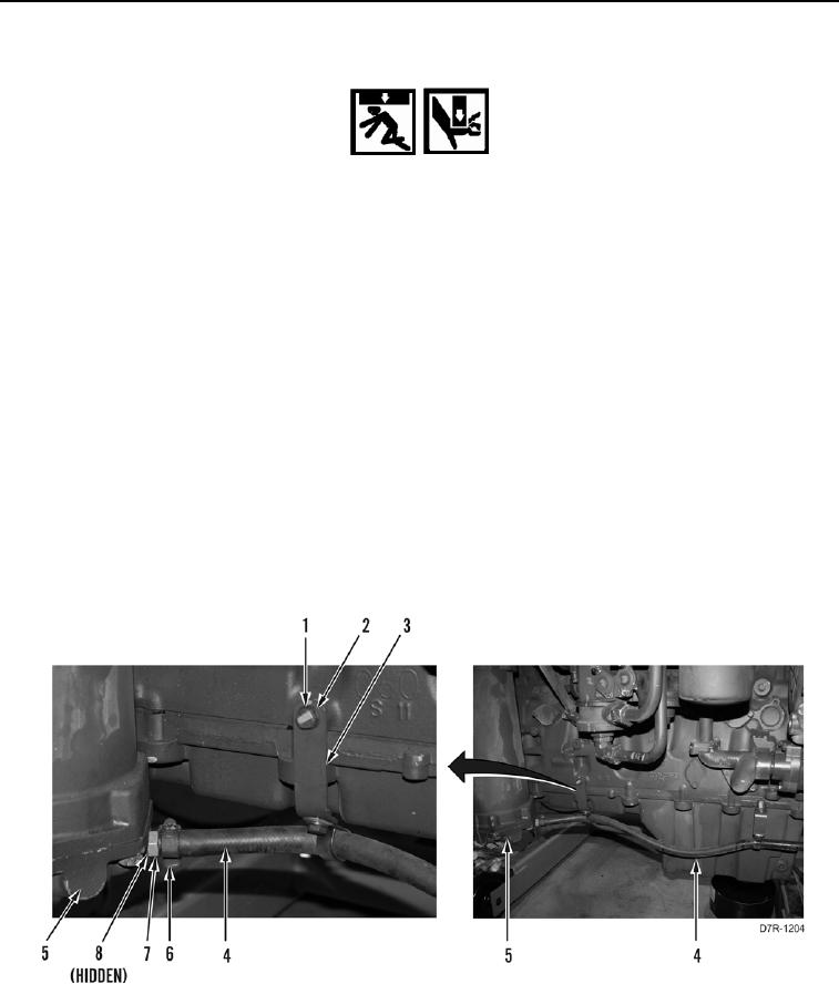
5. Position hose (Figure 33, Item 4) and two brackets (Figure 33, Item 3) on engine.
6. Install two brackets (Figure 33, Item 3), washers (Figure 33, Item 2), and bolts (Figure 33, Item 1) on engine.
7. Install new O-ring (Figure 33, Item 8) and fitting (Figure 33, Item 7) on transmission cooler (Figure 33, Item 5).
8. Install hose (Figure 33, Item 4) on fitting (Figure 33, Item 7).
9. Install clamp (Figure 33, Item 6) on hose (Figure 33, Item 4).
Figure 33. Transmission Cooler Drain Hose.
0059