
TM 5-2410-241-23-2
0059
INSTALLATION CONTINUED
N OT E
Remove all caps and plugs from all lines, hoses and tubes.
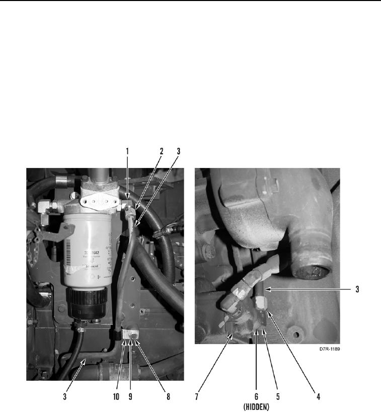
47. Install new O-ring (Figure 50, Item 6) on fitting (Figure 50, Item 5).
48. Install fitting (Figure 50, Item 5) on injection pump (Figure 50, Item 7).
49. Install line (Figure 50, Item 3), P-clip (Figure 50, Item 10), washer (Figure 50, Item 9), and bolt (Figure 50,
Item 8) on engine.
50. Install line (Figure 50, Item 3) and tube nut (Figure 50, Item 4) on fitting (Figure 50, Item 5).
51. Install line (Figure 50, Item 3) and tube nut (Figure 50, Item 2) on fitting (Figure 50, Item 1).
Figure 50. Fuel Line.
0059