
TM 5-2410-241-23-2
0059
INSTALLATION CONTINUED
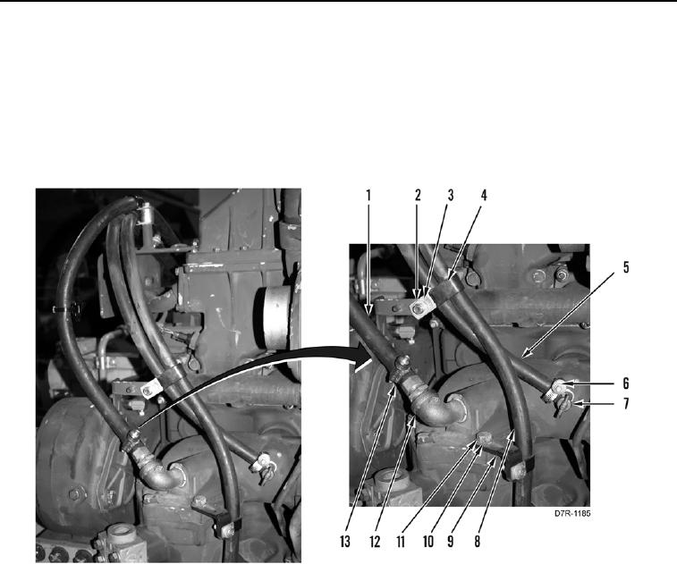
67. Install hose (Figure 55, Item 5) and clamp (Figure 55, Item 6) on valve (Figure 55, Item 7).
68. Install hose (Figure 55, Item 1) and clamp (Figure 55, Item 13) on fitting (Figure 55, Item 12).
69. Position hose (Figure 55, Item 8) and bracket (Figure 55, Item 9) on engine.
70. Install bracket (Figure 55, Item 9), washer (Figure 55, Item 10), and bolt (Figure 55, Item 11) on engine.
71. Install P-clip (Figure 55, Item 4), washer (Figure 55, Item 3), and nut (Figure 55, Item 2) on two hoses
(Figure 55, Items 8 and 5).
Figure 55. Oil Cooler Hoses.
0059