
TM 5-2410-241-23-2
0083
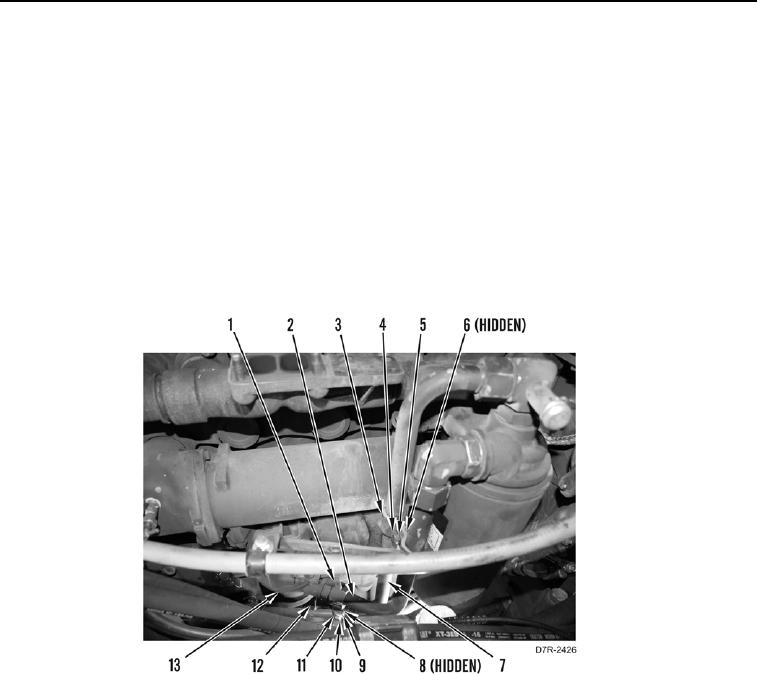
OIL FILTER BASE AND LINES REMOVAL CONTINUED
N OT E
Tag and note routing and orientation of fittings and lines to aid installation.
5. Remove nut (Figure 4, Item 6), bolt (Figure 4, Item 4), two washers (Figure 4, Item 5) and clamps (Figure 4,
Item 3) from lines (Figure 4, Items 7 and 2).
6. Remove nut (Figure 4, Item 8), bolt (Figure 4, Item 11), two washers (Figure 4, Item 9) and clamp (Figure 4,
Item 10) from line (Figure 4, Item 7).
7. Loosen tube nut (Figure 4, Item 12) and remove line (Figure 4, Item 7) from engine filter base (Figure 4,
Item 13).
8. Loosen tube nut (Figure 4, Item 1) and remove line (Figure 4, Item 2) from engine filter base (Figure 4,
Item 13).
Figure 4. Filter Base Lines.
0083