
TM 5-2410-241-23-2
0083
OIL FILTER BASE AND LINES INSTALLATION CONTINUED
N OT E
Orient fittings and lines as noted during removal.
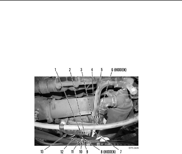
10. Install line (Figure 10, Item 2) on engine filter base (Figure 10, Item 13). Tighten tube nut (Figure 10, Item 1).
11. Install line (Figure 10, Item 7) on engine filter base (Figure 10, Item 13). Tighten tube nut (Figure 10, Item 12).
12. Install clamp (Figure 10, Item 10), two washers (Figure 10, Item 9), bolt (Figure 10, Item 11), and nut
(Figure 10, Item 8) on line (Figure 10, Item 7).
13. Install clamps (Figure 10, Item 3), two washers (Figure 10, Item 5), bolt (Figure 10, Item 4), and nut (Figure 10,
Item 6) on lines (Figure 10, Items 7 and 2).
Figure 10. Filter Base Lines.
0083