
TM 5-2410-241-23-2
0084
REMOVAL CONTINUED
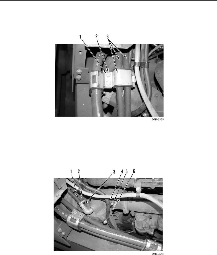
13. Remove two bolts (Figure 3, Item 2) and washers (Figure 3, Item 1) from machine.
14. Position hoses and bracket (Figure 3, Item 3) aside on machine.
Figure 3. Hose Bracket.
0084
15. Loosen clamp (Figure 4, Item 5) and remove hose (Figure 4, Item 4) from valve (Figure 4, Item 6). Position
hose aside.
16. Loosen clamp (Figure 4, Item 2) and remove hose (Figure 4, Item 1) from nipple (Figure 4, Item 3). Position
hose aside.
Figure 4. Oil Cooler Valve.
0084