
TM 5-2410-241-23-2
0084
INSTALLATION CONTINUED
N OT E
Install hoses as noted during removal.
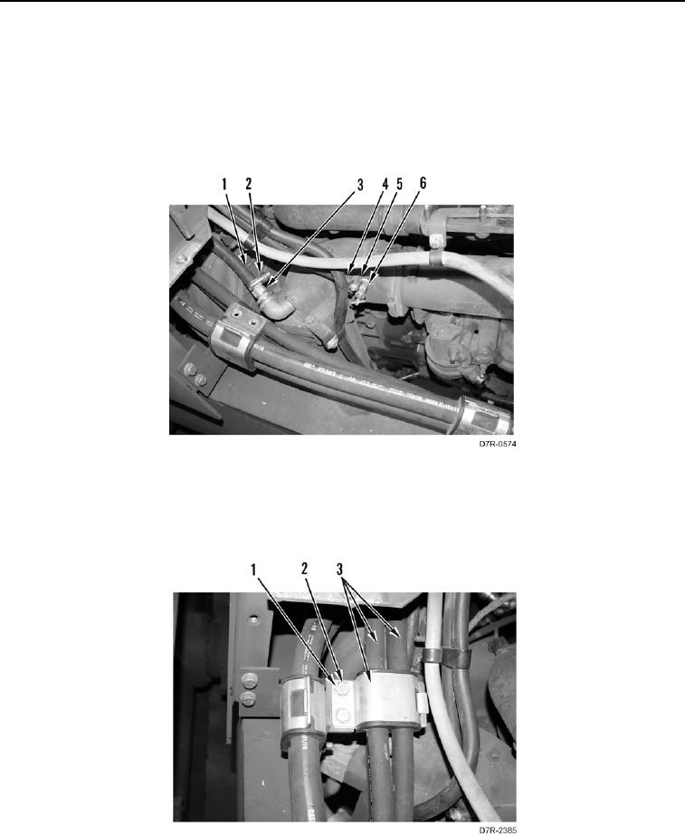
9. Install hose (Figure 10, Item 1) and clamp (Figure 10, Item 2) on nipple (Figure 10, Item 3).
10. Install hose (Figure 10, Item 4) and clamp (Figure 10, Item 5) on valve (Figure 10, Item 6).
Figure 10. Oil Cooler Valve.
0084
11. Install bracket and hoses (Figure 11, Item 3), two washers (Figure 11, Item 1) and bolts (Figure 11, Item 2) on
machine.
Figure 11. Hose Bracket.
0084